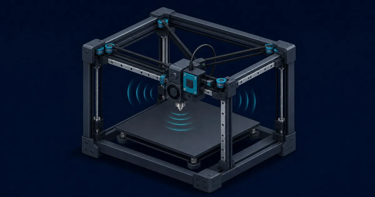
Voron 2.4 Input Shaping: ADXL345 Setup and Tuning
Wire an ADXL345 to a Voron 2.4, run TEST_RESONANCES and SHAPER_CALIBRATE, choose between MZV and EI, and set a max_accel the machine can actually hold.
Input shaping is the step that turns a Voron 2.4 from a machine that can move fast into one that can print fast without ringing. Klipper’s resonance compensation reshapes every commanded move so it stops exciting the frequencies at which your gantry rings. You supply those frequencies. Everything below is about measuring them correctly and then choosing what to do with the numbers.
Two things to settle before you start, because neither is fixed by software.
The machine has to be mechanically right first. Input shaping cancels a resonance; it does not tighten a belt, square a gantry, or seat a rail. If your AB belts are unevenly tensioned or the gantry was never properly squared, calibration returns a frequency that will drift as soon as anything settles. Run QUAD_GANTRY_LEVEL, check belt tension by ear or by frequency, and confirm nothing on the toolhead rattles. If you are still deciding which frame to build, the Voron model comparison covers what each design demands.
Shaping is not free. Every shaper smooths the commanded motion. More robustness against frequency error costs more smoothing, which blurs fine detail. The whole exercise is picking the least smoothing that reliably kills your ringing.
What you need
Klipper supports the ADXL345 plus the MPU-6050, MPU-6500, MPU-9250, MPU-9255, MPU-6515, ICM20948, LIS2DW and LIS3DH families. The ADXL345 talks SPI and is the default assumption in most Voron documentation and toolhead boards. The MPU parts use I2C at 400 kbit/s fast mode and only work on hosts that support that rate, such as a Raspberry Pi or an RP2040 Pico.
Where you attach it matters more than which one you buy:
- A toolhead CAN board with an onboard accelerometer is the tidiest option on a 2.4. Nothing extra rides the drag chain, and the sensor sits where the ringing actually happens.
- A temporary mount on the Stealthburner with a short SPI run back to the host or main board works fine, and is what most builders use if the toolhead board has no sensor.
- The host Pi’s SPI header is only for the temporary case. Keep the cable out of the belt path.
Klipper’s documentation carries an explicit warning worth repeating: make sure the accelerometer, and any screw holding it, does not touch metal parts of the printer. A ground path through the frame is how these sensors and the boards behind them die.
A 2.4 has a fixed bed and a flying gantry, so both X and Y resonances are measured at the toolhead from a single sensor position. That is a genuine advantage over bed-slinger machines, which need the sensor moved to the bed for the Y run or a second accelerometer wired permanently.
Software prerequisites
The analysis runs on the host, not the MCU, and it needs numeric libraries that are not installed by default. On a Debian-based host:
sudo apt update
sudo apt install python3-numpy python3-matplotlib libatlas-base-dev libopenblas-dev
~/klippy-env/bin/pip install -v "numpy<1.26"
Confirm the Klipper virtualenv can actually import it:
~/klippy-env/bin/python -c 'import numpy;'A silent failure here is the most common reason SHAPER_CALIBRATE errors out on an otherwise healthy printer.
Minimum configuration
Three sections, added to printer.cfg. If the sensor hangs off the Raspberry Pi rather than a printer MCU, you also need the host MCU process running:
[mcu rpi]
serial: /tmp/klipper_host_mcu

[adxl345]
cs_pin: rpi:None

[resonance_tester]
accel_chip: adxl345
probe_points:
    175, 175, 20
Set probe_points to the middle of your own bed at a safe Z. For a 350 mm 2.4 that is roughly 175, 175, 20; for a 250 mm machine, 125, 125, 20. Klipper recommends starting with a single centre point rather than a list. Add more points later only if you suspect the resonance changes across the bed.
If the accelerometer lives on a CAN toolhead board, cs_pin and the chip name follow that board’s own documentation instead, and accel_chip must name the same chip.
Sanity-check before measuring
Two commands, in order, every time you change the mounting.
ACCELEROMETER_QUERY reads live values. A healthy sensor at rest reports roughly one g on whichever axis is vertical and near zero on the others. If it errors, the wiring or cs_pin is wrong and nothing after this point will work.
MEASURE_AXES_NOISE gives you a baseline. Klipper puts acceptable readings in roughly the 1 to 100 range. Values in the thousands mean a defective sensor, a bad power feed, or a cable picking up interference. Fix that first: a noisy baseline produces a plausible-looking graph with a peak that is not a real resonance.
Running the measurement
With the printer homed and the bed clear:
TEST_RESONANCES AXIS=X
TEST_RESONANCES AXIS=Y
Each run sweeps the toolhead over a frequency range and writes a CSV to /tmp. The machine is loud and shakes visibly; that is the point. Then generate the graphs:
~/klipper/scripts/calibrate_shaper.py /tmp/resonances_x_*.csv -o /tmp/shaper_calibrate_x.png
~/klipper/scripts/calibrate_shaper.py /tmp/resonances_y_*.csv -o /tmp/shaper_calibrate_y.png
The script prints a recommended shaper type, a frequency and a maximum acceleration for each candidate shaper, and the PNG shows the power spectral density with your resonance peaks in it. Read the graph, not just the recommendation. A single sharp peak is a clean result. Several peaks of similar height mean the machine has more than one thing ringing, which is a mechanical finding, not a shaper choice.
SHAPER_CALIBRATE does the same job entirely from the console and can write the result straight into your config with SAVE_CONFIG. It is faster; the offline script is better when you want to compare shapers or apply a smoothing limit.
Klipper also warns against running auto-calibration frequently. Repeatedly driving the machine at its resonant frequencies wears and loosens hardware. Measure after a build, after a toolhead or hotend change, after a belt change, and otherwise leave it alone.
Choosing the shaper
Klipper ships ZV, MZV, ZVD, EI, 2HUMP_EI and 3HUMP_EI. Ordered from least to most smoothing:
| Shaper | Smoothing | Robustness to frequency error | Typical use |
|---|---|---|---|
| ZV | Lowest | Lowest | Very stiff machine, confident measurement |
| MZV | Low | Moderate | The common CoreXY default |
| ZVD | Moderate | Good | Between MZV and EI |
| EI | Moderate | Good | Frequency varies, or a broad peak |
| 2HUMP_EI | High | Wide band | Two resonances close together |
| 3HUMP_EI | Highest | Widest band | Messy spectrum; usually a mechanical hint |
On a well-built 2.4 the answer is usually MZV, and a result that demands 3HUMP_EI is worth treating as a signal that something is loose rather than as a tuning victory.
Use --max_smoothing on the offline script to cap how much detail you are willing to lose:
~/klipper/scripts/calibrate_shaper.py /tmp/resonances_x_*.csv -o /tmp/x.png --max_smoothing=0.2Klipper suggests storing the smoothing value you settled on, so a later recalibration does not quietly hand you a blurrier result.
The finished config looks like this:
[input_shaper]
shaper_freq_x: 58.4
shaper_type_x: mzv
shaper_freq_y: 44.2
shaper_type_y: mzv
Per-axis shaper_type_x and shaper_type_y are worth using. On a 2.4 the X and Y resonances are produced by different masses, so there is no reason to force one shaper onto both.
Setting max_accel afterwards
Shaping raises the ceiling; it does not set it. Klipper’s own guidance is to choose the lower of two limits: the acceleration at which ringing is still acceptable, and the acceleration at which smoothing has become unacceptable. The second one is easy to miss, because the parts look fine until you compare a sharp corner against the same corner printed slowly.
Klipper also flags a hard case. At very low ringing frequencies, around 25 Hz and below, even MZV creates too much smoothing. The documented next step is to retry with ZV via SET_INPUT_SHAPER SHAPER_TYPE=ZV, which smooths less but is more sensitive to errors in your measured frequency. Below roughly 20 to 25 Hz, though, Klipper’s own advice is to stop tuning and increase printer stiffness or reduce moving mass, because otherwise speed ends up limited by smoothing instead of by ringing. On a 350 mm 2.4 a low Y frequency usually points at the gantry, not the firmware.
To sanity-check a candidate acceleration against your measured frequencies and hotend flow before you commit it, the site’s Klipper input shaper and CoreXY speed calculator does the arithmetic for the 2.4, Trident and V0.2 platforms.
The route with no accelerometer
You can still shape without a sensor. Print Klipper’s ringing_tower.stl at 0.2 to 0.25 mm layers with one or two perimeters and an external perimeter speed of 80 to 100 mm/s, driven by:
TUNING_TOWER COMMAND=SET_VELOCITY_LIMIT PARAMETER=ACCEL START=1500 STEP_DELTA=500 STEP_HEIGHT=5Then measure the distance D in millimetres over which the ringing decays and count the oscillations N in that distance. The frequency is:
frequency = V * N / Dwhere V is the external perimeter velocity in mm/s. It is slower and less precise than an accelerometer, and it cannot show you a second peak, but it is a real measurement and it costs nothing.
Troubleshooting
| Symptom | Likely cause |
|---|---|
ACCELEROMETER_QUERY errors | Wrong cs_pin, SPI wiring, or missing [mcu rpi] |
MEASURE_AXES_NOISE in the thousands | Bad sensor, poor power, or cable pickup |
SHAPER_CALIBRATE fails on import | numpy missing from the Klipper virtualenv |
| Recommended frequency changes run to run | Something loose: belts, rail screws, sensor mount |
| Suggests 2HUMP_EI or 3HUMP_EI | Multiple real resonances; check gantry and frame |
| Corners look mushy after shaping | Smoothing too high; cap it or lower max_accel |
| Ringing returns after a toolhead change | Moving mass changed; remeasure |
What shaping will not do
It will not fix an unsquared gantry, a skewed frame, uneven AB belt tension, or an under-tuned extruder. Pressure advance and input shaping solve different problems and both are needed. And it does not raise your flow ceiling: if the hotend cannot melt fast enough, higher acceleration only gets you to the same volumetric wall sooner. Sort the mechanical side and the hardware choices first, which is what the Voron kit buying guide is for, and if you are still weighing whether to build at all, the Voron 2.4 versus Bambu Lab P1S comparison lays out what a self-built machine buys you.
Sources
Related

Voron 2.4 vs Bambu Lab P1S: Build It or Buy It?
Voron 2.4 and Bambu Lab P1S compared on build volume, speed ceiling, materials, repairability and true cost, with a plain rule for choosing between them.

Voron Kit Buying Guide: What to Check Before Ordering
The Voron kit checks worth making before you pay: printed-part material, extrusion profile, rail grade, bed plate alloy, stepper spec and driver count.

Which Voron Should You Build? V0, Trident, 2.4, Switchwire
Voron V0.2, Trident, 2.4 and Switchwire compared on build volume, motor count and build difficulty, plus what kit sourcing and Klipper tuning demand.